Installation
JOYSTICK MOUNTING
For the past two decades, Cyber-Tech, Inc. has been supplying top quality industrial joysticks. Please refer to Figures 2A and 3A for proper mounting method of the joystick that is used for your application.
SPEC'S

SPEC'S
STANDARD PANEL CUT-OUT DIMENSIONS

FIG. 2A
For all top-mount joysticks, Cyber-Tech, Inc. recommends that edges of all openings be deburred and cleaned to ensure proper seal. (Please refer to Figure 4A for cutout dimensions.) Special Sealed Mounting Kit available, Part # 99-020002-01
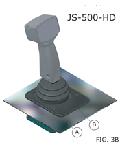
FIG. 3A
For all bottom-mounted joysticks, Cyber-Tech, Inc. recommends that edges of all openings be deburred and cleaned to ensure proper seal. (Please refer to Figure 4A for cutout dimensions.)
FIG. 2B/3B
Cyber-Tech, Inc. recommends that all mounting screws for joysticks be set to a specific torque rate (recommended torque rate = 30 IN-LBS). If you find that 30 IN-LBS is not sufficient we recommend the use of Loctite 272.
A = 30 IN-LBS
B = Front of joystick
(OVER TIGHTENING OF IMPROPER TORQUE SPECIFICATION MAY RESULT IN STRIPPING OR SNAPPING THE SCREW)
FIG. 4A
All of Cyber-Tech, Inc.'s Handy-Grips and Ergo-Grips will fit through the specified cutout hole except the 1801-RB, 8601-RB And EG-950-RB which require a split-mount. Split-mounts consist of removing the handle from the joystick base, mounting the joystick base to the panel and then remounting the handle to the joystick base.
- Center hole cutout = 3.63in
- Mounting screw holes = 0.25in
- Panel install (top mount only) drill and tap for the 10-32 thread
NOTE:
If you have a special installation problem or concern, please call the technical staff at Cyber-Tech, Inc. for assistance. Thousands of successful installations of our controls have been made and we will be happy to share our twenty years of expertise to help you make your installation a success.
CABLE ROUTING
Cable ties are the most common and readily available form of cable attachment on the market. Although Cyber-Tech, Inc. does not promote the use of cable ties due to the potential problems if not properly installed, we understand that sometimes there is no other readily available option for the user. A cable tie can put a tremendous amount of force on the cable and result in faulty and/or intermittent signal transmission. We recommend that the installer use special care not to over tighten the cable ties and be careful not to damage the cable when installing cable ties.
PINCHING THE CABLES
Care should be taken when routing cable to prevent any pinching or cutting of the cable when the unit is operated. A cable loop, with sufficient slack, is recommended at any point where thee cable may be put under stress during operation of the unit. Cyber-Tech, Inc. recommends that a rubber grommet be used if the cable must be routed through holes in the sheet metal or steel frames to prevent the cable jacket from excessive wear or being cut when the unit is in operation.
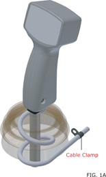
EXCELLENT CABLE ROUTING METHOD

GOOD CABLE ROUTING METHOD
POOR CABLE ROUTING METHOD
FIG. 1A
As shown in figure 1A Cyber-Tech, Inc. has proven over the past 20 years that this is the preferred method of cable attachment. By using the coil method around the control stick, in conjunction with a cable clamp located a minimum of 5 inches from the last coil. We have proven that the flex point of the cable is maintained on the back side of the cable clamp.
By using FIG. 1A you can insure proper switch life of a unit, non-flexed point on the cable, and best overall results. This is Cyber-Tech, Inc.'s preferred method of control stick attachment.
FIG. 1B
As shown in figure 1B Cyber-Tech, Inc. understands the importance of ensuring a solid non flex-point on the cable. If FIG. 1A is not obtainable, we recommend FIG. 1B as a secondary option, although it is not as effective as the coil method. Cyber-Tech, Inc. feels by using a cable tie in conjunction with the cable clamp it would reduce the overall flex point on the cable.
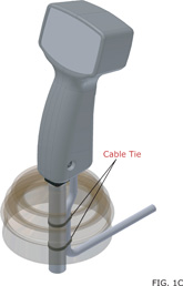
FIG. 1C
Cyber-Tech, Inc. does not endorse FIG. 1C. If the installation leaves no other choice we recommend the use of 2 cable ties.
The installer must leave adequate cable slack. This cable method will result in a dramatic flex-point of the cable resulting in broken or pinched wires.
NOTE:
If you have a special installation problem or concern, please call the technical staff at Cyber-Tech, Inc. for assistance. Thousands of successful installations of our controls have been made and we will be happy to share our twenty years of expertise to help you make your installation a success.
SPIKE SUPRESSION
STANDARD SWITCHING THAT REQUIRES DIODE PROTECTION
In the early days when electro-hydraulic control systems were applied to industrial equipment switch life was a major. When inductive loads are turned off, they produce large voltage spikes that are feed back to the switch contacts, causing premature failure of the switches. Valve manufacturers recommended that a diode be installed, as close as possible, directly across the valve coil to suppress this voltage spike. However, the diode was not supplied with the valves and most equipment manufacturers found it difficult and costly to install the diodes on every valve. Another problem is that the diode on the valve does little to eliminate stray voltage spikes from other inductive sources that are coupled through the machine wiring back to the switches.
Poor Switch Life
(Click To View Larger Image)
CYBER-TECH, INC. STANDARD BUILT IN SWITCH DIODE PROTECTION.
In 1985, after trying to work with major suppliers of switches to obtain a switch that would hold up and give reasonable life in this environment, Cyber-Tech, Inc. developed a proprietary line of pushbutton and rocker switches rated 10,000.00 cycles at 5 amps inductive. These switches have a built in diode to provide the necessary suppression of the damaging voltage spikes that get back to the switch. The Cyber-Tech, Inc. switches have a proven record for reliable operation in the field for the past seventeen (17) years.
Good Switch Life
(Click To View Larger Image)
STANDARD SWITCH WITH LIMITED SPIKE PROTECTION
Other suppliers have tried to develop cheap diode packages that are installed in the machine cabling to solve these problems. The diode packages are less effective because they are not located at the switch contact or the valve coil. They do very little to protect the switch contacts from stray voltage spikes from other unprotected inductive sources associated with the equipment operation. Some of these diode packages are very difficult and labor intensive to install (requiring the cutting the cable jackets, stripping wires and smoldering terminals). Every splice in the wiring is another potential vibration problem.
Fair Switch Life
(Click To View Larger Image)
CYBER-TECH, INC. RECOMMENDED DIODE PROTECTION
The most effective way to protect the control switching is to place a diode directly across the valve coil as recommended by the valve manufacturer and place an addition diode directly at the switch output contact to eliminate any spikes that are coupled back to the switch.
Excellent Switch Life
(Click To View Larger Image)


